This guide serves as a tool to ensure that PLC programs are properly documented, simple, and easy for engineers and maintenance personnel to understand. Our goal is to steer clear of overly complicated spaghetti code, making the logic easy to modify without hours of unwinding.
Program Documentation: Programs must be logically constructed and accompanied by detailed documentation. This includes rung descriptions, logical tag names, logical separation of programs, sub-routines, tasks, and so forth. Understanding the program should not be a riddle but a straightforward exercise. A high-quality program starts with thorough documentation. It’s essential to logically organize and adequately present your PLC programs to facilitate readability and future changes. Key aspects to consider in your program documentation include:
- State machines, sometimes known as sequential function charts, should be clearly documented. This includes denoting states, transitions, and events. Each state should be uniquely identifiable with logical names and accompanying descriptions, explaining its role in the context of the entire program. Transitions between states and the events that trigger these transitions should be clearly marked and explained, ensuring thorough understanding.
- Similarly, process control logic, whether they are feedback control systems like PID controls or batch sequencing, should be explicitly detailed. Process variables, control variables, set-points, tuning parameters, and loops should be logically named and have clear definitions. The description and function of each control block, the strategy for tuning, and sequencing steps should be well documented. Any interlocks, fail-safes, or overrides that affect the control logic should be highlighted.
- Documentation should encompass logical and intuitive rung descriptions and tag names. Every rung in the code must come with a description, summarizing its function in the program. Logical tag names enhance understanding of the code, giving meaningful context to data storage and processing functions.
- Maintain logical separation of programs, sub-routines, and tasks according to their respective functions. Segmentation aids comprehension by limiting the scope and role of each code block. Through this, it becomes simpler for other engineers to navigate, modify, or debug the PLC program.
Here is an example rung from a state machine sequencer. Clear rung descriptions and logical tag names should always be used:
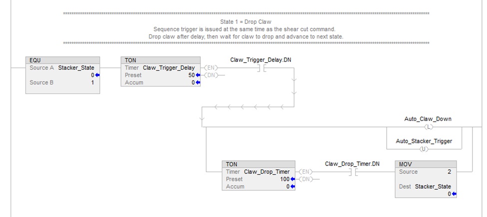
Remember, a well-documented program provides a roadmap to engineers and maintenance personnel, making it easier to read, understand, modify, and maintain the PLC program, enhancing efficiency and reducing downtime. Moreover, it serves as an invaluable tool for training new staff and provides a benchmark for future automation tasks.
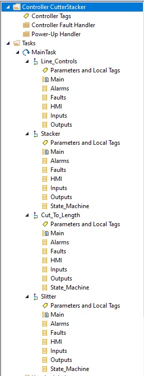
Program Hierarchy: Below is an image of the program and sub-routine hierarchy located in the main task of a PLC project. This PLC controls a standalone machine, yet there are four programs within the hierarchy. Treating each sub-system as a standalone system and programming it accordingly promotes modularization, where each subsystem’s program works independently yet can interact with others when needed. This ensures uninterrupted progression of tasks while retaining the flexibility to share global data across these standalone programs.
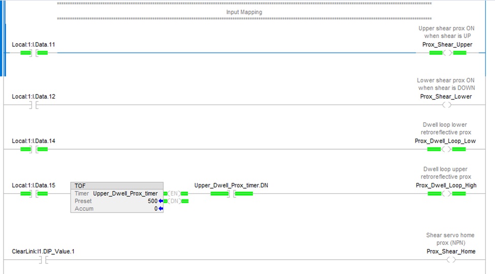
Input & Output (IO) Logic Mapping: Program logic should not directly reference physical IO tags. Instead, these should be mapped to tags/variables with logical names in a dedicated IO mapping routine, ideally, an “Inputs” and “Outputs” routine. This approach allows for easy changes and remapping of IO without having to trace those inputs or outputs throughout the PLC logic. For analog inputs or other non-binary data types, these routines are a great place to scale or manipulate the data as needed for the core program logic.
Example input mapping:
Example output mapping:
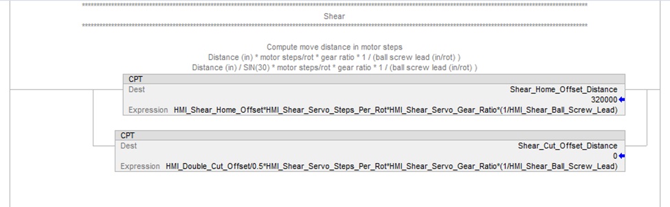
Human-Machine Interface (HMI): Often, the data transferred to and from an HMI needs to be altered, scaled, limited, or converted into units that are suitable for HMI display or use in PLC logic. It is recommended to use an “HMI” routine within the PLC for this data manipulation. Although many HMIs offer features like unit scaling and value limits within their program, it is advisable to avoid this practice. Instead, this should be carried out in the PLC. The rationale behind this is that when an HMI project migration is needed due to the discontinuation of an HMI, having the data pre-formatted in the PLC simplifies the process. This approach enhances the feasibility of migrating to HMIs from different brands or manufacturers.
Here is an example of where HMI input data is used to calculate servo motor steps inside an HMI subroutine:
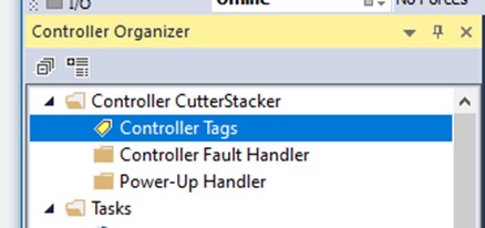
Controller and Local Tags: Tags should use logical, descriptive names. While controller tags typically tend to be global and can be referenced in each program/routine, tags within a specific program or task should be set to local. This rule only deviates when they need to be referenced in other programs within the PLC or accessed remotely. This makes it easy to reuse code and scale systems that have similar or identical components.
In Studio 5000, global tags reside here:
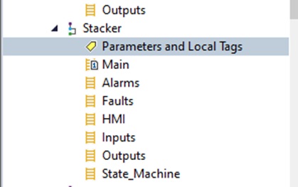
Local tags reside within the program as shown here:
Faults and Alarms: Faults and alarms, while often used interchangeably, have distinct differences and roles in industrial control systems. Correctly understanding and implementing these can drastically improve a system’s performance, reliability, and safety.
- Faults are serious system abnormalities often indicating hardware failures or operational errors that prevent part or all of a process from executing properly. PLCs often have dedicated fault routines that are triggered when a fault condition is detected. It’s crucial to program these routines to handle each possible fault condition. Handling may include stopping critical processes safely, attempting system recovery, or preparing the system for maintenance intervention. As a best practice, all notable faults should be logged with timestamp, type of fault, and any relevant system data at the time of the fault. This information is essential in troubleshooting the root cause of the faults.
- Alarms function as real-time notifications of issues that need attention but don’t necessarily halt the process. They point to issues like a motor running hotter than usual, levels nearing limits, or even minor issues that have the potential to develop into major problems if left unchecked. Just like faults, alarms require a dedicated alarm routine. This routine should monitor conditions that, if met, trigger specific alarm notifications. This translates into instant acknowledgment of developing problems and their swift handling, minimizing damage and downtime.
- Faults and alarms should be logically set in the PLC and represented on the HMI or SCADA systems to ensure that operators are instantly alerted.
- Furthermore, the fault and alarm strategy should follow efficient management principles to ensure they are effective and not overwhelming. This includes rationalizing the number of alarms, prioritizing them effectively, and ensuring they are annunciated in a way that gives sufficient information to operators, allowing them to take necessary corrective actions.
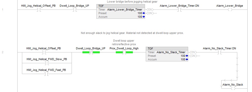
Example alarm rungs:
Example fault rungs:
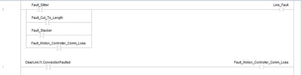
In a nutshell, incorporating an effective “Faults” and “Alarms” routine into your PLC programming strategy contributes significantly to identifying and managing system abnormalities, enhancing the overall performance, safety, and lifespan of the system.
Safety Measures: Best practice is to use redundancy and always include programmatic interlocks to shut off outputs and remove hazardous energy sources.
- This should be programmatically performed even in the presence of physical hardware safety devices such as interlocks and safety relays.
- A machine/system must never be solely dependent on programmatic interlocks. While hardware safety measures are vital, including software-based programmatic interlocks offers a second layer of protection. They prevent certain operations from occurring if certain conditions aren’t met within the program.
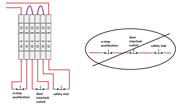
- Whenever possible, individual safety devices should be tapped at their appropriate circuit location and fed into digital inputs. Safety status and circuit interruptions can then be displayed on an HMI to quickly identify where the interruption occurs. An example is e-stop pushbuttons on a safety circuit and quickly identifying which one is pressed.
- Sometimes inputs may not be available for safety devices. When practical, safety device conductors should be run back to the main control cabinet and individually terminated on terminal blocks rather than connected in series in the field. The terminal blocks can then be jumpered from one device to the next which completes the safety chain. This makes troubleshooting an interrupted circuit quick and easy with a multimeter at one location.
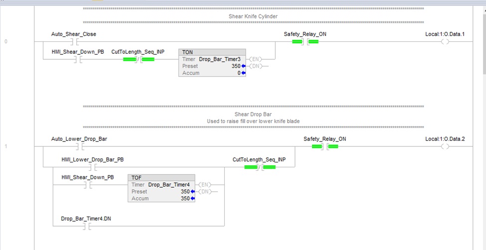
Example of a programmatic interlock:

In this example, let’s assume that if the safety relay is not energized, and power is interrupted to the PLC outputs or output relays. This means the main air solenoid is disabled regardless of programmatic state of the PLC output. However, we still include a redundant programmatic interlock where if safety power is not detected, we do not energize the output. The greater the hazard, the more critical this becomes.
Standards and Frameworks: International Electric Code (IEC) 61131 is a well-established reference standard for the industry. Specifically, IEC 61131-3 is an excellent source for understanding data types, information storage in memory, and its usage in logic within the PLC. This standard, designed specifically for programmable controllers, provides guidelines and hierarchical structures for the different elements within a PLC system:
- The standard consists of several parts, and each serves a specific purpose. Part 3 of the standard, IEC 61131-3, is particularly notable as it provides robust guidelines for programming languages for PLCs.
- There are five languages that cater to different programming requirements and styles. These include ladder diagram (LD), structured text (ST), instruction list (IL), function block diagram (FBD), and sequential function chart (SFC)
- The standard specifies basic data types like BOOL, BYTE, WORD, DWORD, LWORD, SINT, INT, DINT, LINT, USINT, UINT, UDINT, ULINT, REAL, LREAL, TIME, DATE, TIME_OF_DAY, DATE_AND_TIME, STRING, BYTE_STRING, and WSTRING. Moreover, it allows creation of user-defined custom data types for more complex data structures.
- IEC 61131-3 provides for well-structured task organization. It outlines three types of tasks — cyclic tasks, event tasks, and interrupt tasks — each with specific prioritization and execution sequences depending on real-time requirements.
- IEC 61131-3 proposes a technique of building and managing libraries for re-usable codes. This promotes code reuse across different projects and enhances code management, scalability, and readability.
- Configurations and Resources: The standard clarifies the segregation of hardware and software components. It deals with system configurations thematically including resources, tasks, and global variables.
Following these IEC 61131-3 standards ensures PLC programs are compliant with universally accepted practices. This not only increases software robustness and maintainability, but also facilitates code portability between different PLC brands implementing IEC 61131-3 (most do).
Reducing Hardware Reliance: Aim for a reduced reliance on sensors, instrumentation, actuators, etc, possibly down to zero. While zero is not often realistic, any addition of devices/complexity should be justified and should serve a clear purpose. This will reduce programmatic overhead and development time and increase maintainability. The KISS – “Keep It Simple Stupid” approach can be effectively utilized. It aims to minimize complexity, emphasizing on fewer but well-thought-out complexities.
In conclusion, a well-engineered system is simple, easy to read and understand, and elegant in its design. It is the developer’s responsibility to ensure that the code is efficiently documented, logical, and that a safe working environment is maintained. Treating this guide as a pillar to PLC programming will help ensure that we are providing systems that are safe, reliable and efficient.
If you require assistance with PLC programming, please email info@copecontrols.com or call (240) 397-9096 to inquire about our services.